Guide:Wiring Logic Gates Reference Guide
Contents
The Wiring Lab
Welcome to the Wiring Lab!
Here we have all the amenities for you to test and experiment with all the electrical logic gates in the known universe! These include the Timer, X-Or, (definitely) Not, And, Or, and/or Latch Gates! (See what I did there?)
First I'll show you the wiring scheme for each gate, connected to Tiny Wall Switches (![]() ) as inputs and Bulbs (
) as inputs and Bulbs (![]() ) as outputs which simply show whether a device is giving power or not.
) as outputs which simply show whether a device is giving power or not.
I'm Dr. Professor Storm, PhD, and I'll be your lab instructor today! The green guy here is Bubsy, my Flowerfaceasaur, and his favorite ball.
Crafting Logic Gates
First off, all logic gates are crafted at the Wiring Station:
Most gates require a AA Battery ![]() , silicon board
, silicon board ![]() and copper wire
and copper wire ![]() for each connector.
for each connector.
These components can all be crafted at an Atomic Furnace, which is the highest upgrade to the Primitive Furnace.
The Logic Gates
 Timer (0.5 Sec)
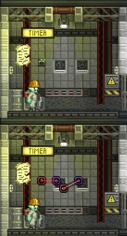
Our first chamber is the Timer. As of the time this guide was written, only the Half Second timer has been implemented into the game.
As a note, purple nodes represent an input while a red node is an output. This gate only has one input so there is only one switch.
The Timer is pretty straight forward. But the important thing to remember is that the loop begins only when the switch is OFF (red). If you wanted a timer loop to begin when the switch were ON, consider hooking the timer to a NOT gate.
 XOR Gate
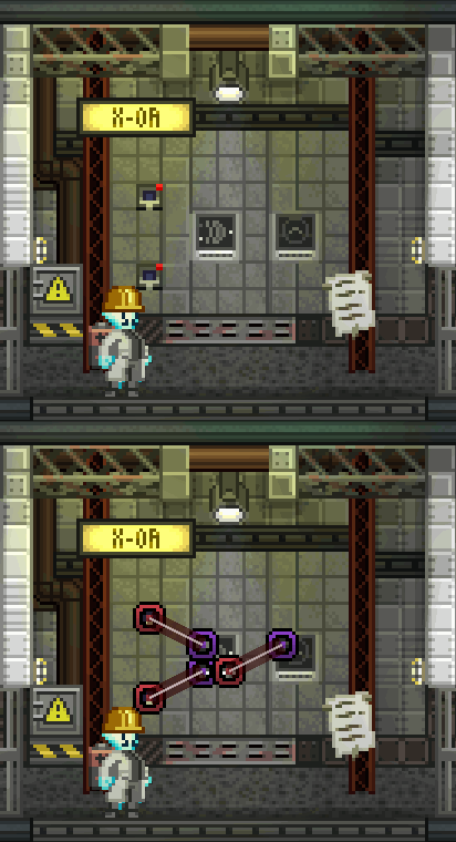
Next is the XOR, or Exclusive Gate
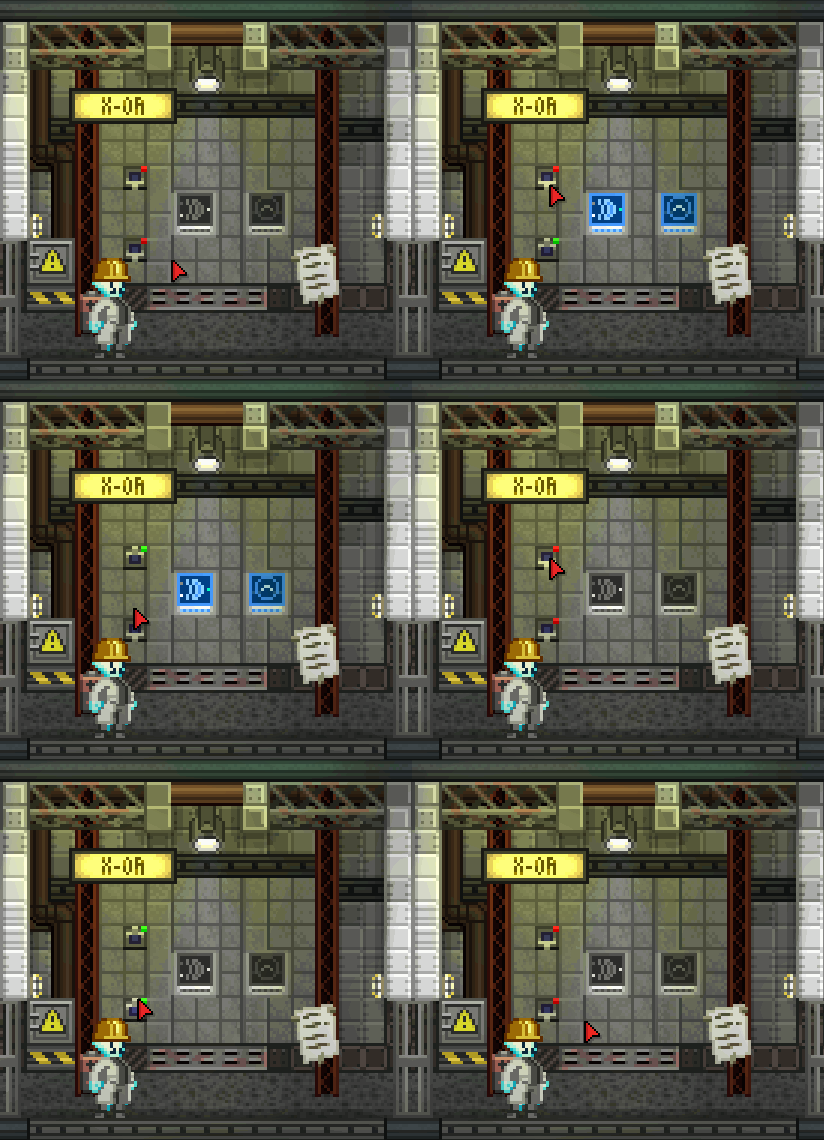
This gate has two inputs so there are two switches, both work together and act as the same type of input.
The XOR gate allows you to simultaneously control an object through two switches, where the output of the gate changes dynamically with each flip of either switch. This could be used to, for instance, control a secret door from both sides of it using a secret hidden switch on one side, and a regular visible switch on the other. This way you will never get trapped inside the secret room!
 OR Gate
This is the OR gate (Or is it?... Don't worry, it is.)
Again, it has two inputs so it has two switches as well. (Bubsy, get out of the camera! This is science we are conducting! I cant throw the ball right now!)
This gate looks at both of its inputs and, if at least one of them is on, it turns on our bulb. Simple as that.
So simple in fact that this gate can actually be considered useless because it acts as though both switches were connected to the input on the bulb anyway. Since Starbound has no limit on the number of inputs or outputs on a single node, there is no point in having an additional logic gate between the switch and the bulb.
 AND Gate
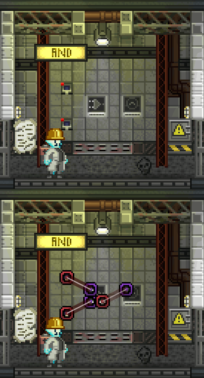
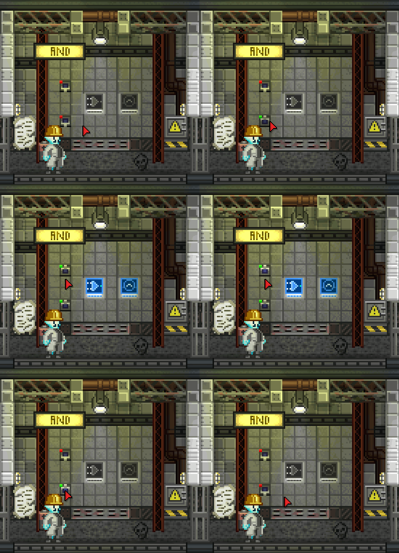
And this is the AND gate!
Again, there are two inputs.
In this case, the bulb will turn on ONLY if BOTH inputs are turned ON. Also pretty simple, but this could be used in creative ways to, for instance, prohibit entrance to a certain area unless two switches are flipped in different parts of a base.
 Latch Gate
Finally, here is the Latch gate.
This gate is a little more complex. It has two inputs but the top input acts as an enabler for the bottom input. As such, I've connected the top switch to a handy sign which will tell us if the bottom switch is enabled or disabled.
You can see I have a lot of notes on this guy, hah!
As I said, this guy is compli- BUBSY I SAID I CAN'T PLAY FETCH RIGHT NOW, QUIT BEING A CAMERA HOG! (*Flowerface raspberry disappointed noise*) Later, Bubsy, Later!
OK, So the Latch gate acts as a sort of switch lock mechanism. If the top input is not enabled, then the bottom input can't do anything to the bulb and the output. But, similarly, the top input doesn't actually do anything to the output - it only controls the second input.
Conclusion
There you have the Logic Gates of the Starbound Universe! There are more in the real world though. In case you're curious, you can learn more here
OK Bubsy, NOW we can play ball!
C'mon, fetch! FETCH! ...*sigh*
Further References
SeaJay's Guides on Basic Wiring and Advanced Wiring


